


Installation Guide: E-Bike Conversion Kit
Complete step-by-step guide for installing a conversion kit on any standard bicycle — from unboxing to your first test ride, no specialist tools required.
Contents
Introduction
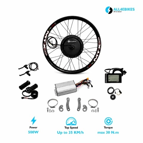
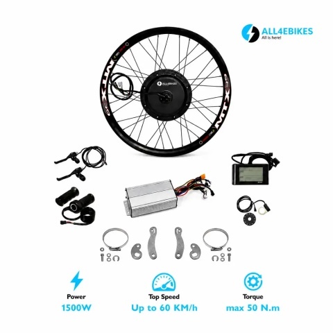
Before starting the installation, unpack your conversion kit and verify that all components are included. Inspect each part for any shipping damage and compare against the list below.
If you haven't ordered yet, or you're double-checking before you start, confirm your bicycle meets the four core compatibility criteria — wheel size, axle type, brake type, and sprocket count — in our bike compatibility verification guide. Any standard bicycle meeting those four criteria can take a kit from the 250W-3000W range, as long as your wheel size is offered for the power you choose (the 500W kit comes in 27.5 and 29 inch, the 3000W kit in 26 and 27.5 inch). This walkthrough applies whichever kit you've chosen.
Typical kit contents
No specialist tools are needed. Everything below is available in any standard bicycle toolkit:
Fitting the sprockets
- Place the motorised wheel on a stable surface.
- Thread the sprockets onto the threaded side of the motor axle.
- Hand-tighten until secure.
- The sprockets will self-tighten further during normal use through the pedalling force.
Fitting the brake disc
- Align the disc with the mounting holes on the motor flange.
- Insert all bolts before tightening any of them.
- Tighten in a star pattern — do not fully tighten one bolt before moving to the others.
- Check that the disc spins freely without touching the flange.
- Check the rotation direction arrow on the tyre sidewall and orient it correctly.
- Insert the inner tube valve through the valve hole in the rim.
- Fit the tyre onto the rim by hand — avoid metal tyre levers which can pinch the tube.
- Check all the way around that the inner tube is not trapped between the tyre bead and the rim.
- Inflate partially (1–2 bar) and check that the tyre is seated evenly around the full circumference.
- Inflate fully to the pressure recommended on the tyre sidewall.
- Remove the original rear wheel from the bicycle.
- Insert the motorised wheel into the frame dropouts, paying attention to motor cable orientation — the cable should exit on the left-hand side of the frame, towards the controller.
- Ensure the axle sits fully and squarely in both dropouts.
- Fit the washers in the correct order as shown in the kit instructions.
- Thread the axle nuts on by hand, then tighten firmly and evenly with the adjustable spanner.
- Check that the wheel is perfectly centred in the frame and does not rub against the brake pads.
Brake levers with cut-off sensors
- Slide the brake levers onto the handlebars, leaving room for the display and throttle.
- Angle them comfortably for your natural hand position.
- Tighten the clamp bolts with the 5 mm Allen key.
- Connect the brake sensor cable to the corresponding port on the controller — when a brake is applied, the motor cuts out immediately.
Twist throttle (included in the kit)
- Slide the twist throttle onto the right-hand side of the handlebars.
- Check that it rotates freely through its full range of motion without binding.
- Adjust the position and tighten firmly.
Your kit includes an SW900 display. If you bought the UKC1+ separately as an upgrade, the mounting procedure is the same.
- Slide the display bracket onto the handlebars, preferably in the centre or slightly right of centre.
- Position the display so the screen is readable without looking away from the road.
- Tighten the bracket mounting screws.
- Connect the display cable to the dedicated port on the controller — this is typically a keyed connector that can only be inserted one way.
Once the display is mounted and wired, check that parameter P03 matches the voltage of the battery you chose (the battery is bought separately) and that P06 matches your wheel size — and it's worth understanding what each button does before your first ride. Our complete SW900 display guide covers every button function, all five riding modes, the full error code table, and every P01–P16 parameter in detail.
The PAS (Pedal Assistance System) sensor detects pedal rotation and activates the motor proportionally. Without the PAS, the motor operates only via manual throttle.
- Remove the left crank arm if necessary to gain access to the bottom bracket area.
- Slide the PAS sensor ring onto the axle, next to the bottom bracket shell, on the left-hand side of the bike.
- Slide the magnet ring onto the axle with the magnets facing the sensor.
- Set a gap of 1–3 mm between the sensor face and the magnets — too close may obstruct rotation, too far reduces sensitivity.
- Secure the magnet ring with the included cable tie or clamp.
- Refit the left crank arm.
- Connect the PAS cable to the corresponding port on the controller.
The controller is the brain of the system — it manages power flow between the battery and the motor. Connect wires in the order below and verify each connector before moving to the next.
Standard connections
- Motor phase wires (3 thick wires: yellow, green, blue) — bullet or XT60 connectors
- Hall sensor connector (5-pin) — detects motor rotor position
- PAS connector — thin cable from the sensor mounted at the bottom bracket
- Brake connectors (left and right) — cut motor power when brakes are applied
- Throttle connector (twist throttle)
- LCD display connector
- Speed limit connector (optional) — jumper or separate cable
- Front light connector (optional) — if the kit includes a headlight
- Battery positive and negative — connect last
Tips for correct wiring
- Match wire colours before forcing any connector.
- XT60 connectors have one correct orientation — do not force them.
- Verify that each connector is fully seated, with an audible click where applicable.
- Secure all cables with plastic cable ties, well clear of the chain, wheel, and any moving parts.
Matching controller amperage to your motor
If you're installing a replacement or upgraded controller rather than the one supplied with your kit, amperage must match the motor's rated power. A controller that's too small will underperform and run hot under load; one that's too large can push more current through the motor windings than they're designed to dissipate, shortening the motor's life. Our controller amperage guide breaks down which controller — 17A, 22A, 26A, 35A, 45A or 60A — pairs with which motor power, and explains how to read the label on your current controller if you're not sure what's already installed.
Pre-ride checklist
- ✓ All wheel axle nuts are tightened firmly
- ✓ Wheel is centred and does not rub against brake pads
- ✓ Brakes work correctly and sensors cut motor power when applied
- ✓ Throttle responds smoothly through its full range
- ✓ Display powers on and shows battery level
- ✓ All cables are secured with ties and clear of moving parts
- ✓ PAS sensor is at the correct gap from the magnet ring
Bench test with the rear wheel off the ground
- Lift the rear wheel off the ground using a bike stand or with assistance.
- Connect the battery.
- Power on the display.
- Apply the throttle gently — the wheel should spin smoothly.
- Test the brake sensor — applying a brake should cut motor power immediately.
- Test the PAS — rotate the pedals by hand, the motor should engage after 1–2 rotations.
Troubleshooting common installation problems
Even a careful installation can throw up a few issues on the first ride. Below are the problems installers report most often, and how to resolve each one without stripping the whole build back down.
Wheel wobbles or rubs against the frame
This is almost always an axle seating issue rather than a wheel defect. Loosen both axle nuts, push the wheel fully forward into the dropouts so the axle flats sit flush against the frame, then re-tighten evenly on both sides while checking the gap to the chainstay is equal left and right. A wheel tightened unevenly will pull slightly to one side and rub the brake pad on that side only.
Throttle is unresponsive or cuts in and out
Start with the connector: unplug and reseat the throttle connector at the controller, checking for bent pins. If the fault persists, check that a brake lever isn't being lightly pressed by a badly routed cable housing — brake sensors cut throttle output even with a very light touch on the lever. Twist throttles that cut out intermittently are sometimes caused by the cable being pinched under the handlebar grip clamp; loosen the grip and re-route the cable with a little slack.
PAS assist is delayed, jerky, or doesn't engage at all
Recheck the 1–3mm gap between the sensor and magnet ring described in Step 7 — a gap that's too wide is the single most common cause of unreliable PAS response. If the assist engages but feels jerky, the sensor may be misaligned so it only catches some of the magnets on each rotation; loosen the mounting clamp, rotate the sensor a few degrees, and test again.
Display shows an error code immediately after connecting the battery
A code appearing the moment you power on almost always points to a connector, not a defective part. Codes in the 10–13 range typically mean a communication or wiring fault between display and controller; code 6 usually means the display's voltage parameter doesn't match your battery. See the full SW900 error code table for what each number means and the exact fix.
Motor spins but the wheel doesn't move properly, or spins the wrong way
If the wheel spins backwards when the throttle is applied, two of the three motor phase wires are swapped — power off, swap any two of the three phase bullet connectors, and retest. If the motor buzzes or vibrates without turning at all, the Hall sensor connector is the more likely culprit; reseat that 5-pin connector fully and confirm none of the pins have pushed back inside the housing.
Weatherproofing your installation
How you route and protect your cabling during installation has a bigger effect on long-term reliability than most people expect — more failures come from water finding its way into a loose connector than from any single component simply failing on its own.
- Route the controller and all connectors away from direct spray off the front and rear tyres wherever your frame allows it.
- Leave a small drip loop in any cable that runs downward into a connector, so water travels past the connector rather than into it.
- A dab of dielectric grease on connector pins before mating them displaces moisture and meaningfully reduces corrosion over a winter of riding.
- Check the IP (Ingress Protection) rating printed on your controller and display housing — this tells you exactly what level of splashing or spray each component is designed to tolerate.
Not sure what an IP54 or IP65 rating actually covers, or whether it matters for how you ride? Our IP54 vs IP65 water resistance guide explains the difference in plain terms and which components are worth prioritising if you commute in all weather.
Related setup guides
Once your kit is installed and running, these guides cover the details this walkthrough only touches on briefly:
- Which controller fits your kit — amperage explained and how to match a replacement controller to your motor.
- SW900 display complete guide — every button, riding mode, and the full P01–P16 parameter list.
- Is the kit compatible with my bike? — the four criteria to check before you order.
- IP54 vs IP65 water resistance — what those ratings mean for riding in the rain.
Frequently asked questions
How long does it take to install an e-bike conversion kit?
On average 2–3 hours for a first-time installer. With experience or a second pair of hands, installation can be completed in under 90 minutes. Cable routing and mounting the controller to the frame typically takes the most time.
Do I need specialist tools?
No. You only need Allen keys (2.5, 3, 5 mm), an adjustable spanner, a Phillips screwdriver, tyre levers, and a bicycle pump. All are standard tools available in any bike shop or online.
Why must the battery be connected last?
Connecting the battery before all other connections are finalised can cause short circuits or permanently damage the controller if any connector is incorrectly oriented or if bare wires are in contact. Always connect the battery last, after a visual check of every other connection.
The motor does not start after connecting — what should I check?
Check in this order: (1) the battery is charged and connected correctly; (2) the display is powered on and not in a locked mode; (3) no brake levers are being held — brake sensors cut motor power; (4) the Hall sensor connector is fully seated; (5) the phase wires are connected in the correct order. If the motor vibrates without rotating, the phase wire order is reversed — swap any two of the three phase wires and test again.
Does the kit work without the PAS sensor?
Yes. The kit operates via the twist throttle without the PAS sensor connected. The PAS adds automatic motor assistance when you pedal. If you choose not to fit the PAS, simply leave the PAS connector disconnected at the controller — it does not affect the function of any other component.
Can I install the kit on my own, or do I need help?
Most riders install a kit solo in 2–3 hours using the steps above. Having a second pair of hands makes two moments easier — holding the wheel steady while you thread the axle nuts, and holding the frame steady while torquing bolts — but neither step strictly requires a helper.
What's the difference between a geared hub motor and a direct drive motor?
Geared hub motors use an internal gearbox and a freewheel clutch, so they're lighter and let the wheel spin freely without drag when the motor is off — better for pedalling efficiency and hill starts. Direct drive motors have no internal gears, which makes them simpler and virtually maintenance-free, but heavier and with slight drag when unpowered. All4eBikes MTX kits use gearless direct-drive hub motors: no internal gears to wear, near-silent running and virtually no maintenance.
Do I need to reset or recalibrate the display after installation?
No calibration is required for the SW900 display included with All4eBikes kits, but since the battery is bought separately, enter the settings menu once to check that P03 matches your battery voltage and that the wheel size parameter (P06) matches your actual tyre diameter for an accurate speedometer. Full button-by-button instructions are in our SW900 display guide.
Conversion Kits
250W → 3000W. Romania stock. Free shipping over 500 RON. 24-month motor warranty, 12 months on the other components.

Reviews